|
|
|

|
Irradiance measurements
|
|
 Request for information Request for information
Radiated optical energy can be quantified as a radiant flux, a measure in energy per second (Watts) radiated from a source. The radiated optical energy can then be correlated with human vision (photometry) as defined in the CIE to obtain a spectral luminous efficiency function to characterize the vision of an average human observer.
Both, radiometric and photometric quantities can be measured with an irradiance calibrated spectrometer system. Radiometric quantities are radiant energy (in Joule), Radiant power or flux (in Watt) or irradiance (Watt per cm˛). Related photometric quantities are luminous flux (lumen) or illuminance (lux or lumen per m˛).
| Radiometry | Symbol | Unit |
| Radiant flux | Φ e | W |
| Radiant Intensity | Ie | W/sr |
| Irradiance | Ee | W/m˛ |
| Radiance | Le | W/m˛ sr |
| Photometry | | |
| Luminous flux | ΦV | Lm |
| Luminous intensity | IV | lm/sr = cd |
| Illuminance | EV | Lm/m˛ = lx |
| Luminance | LV | Cd/m˛ |
Overview about physical and physiological quantities
Photometry is the measurement of visible light. Unlike radiometry, it is not a purely physical measurement and is calculated considering a 'standard' human visual perception. This is attained by multiplying the radiometric data by the luminous efficacy curve (see figure below) and integrating the product over the visible range (380 – 780 nm).
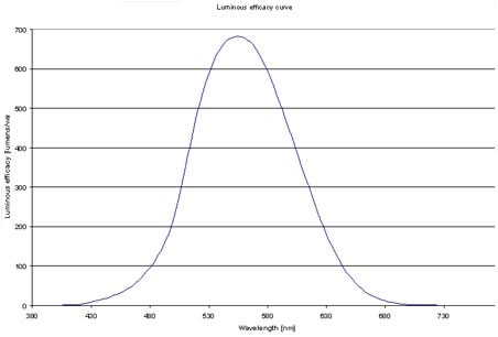
Luminous efficacy curve
Irradiance measurement setup
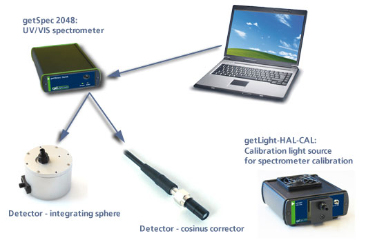
Spectral Irradiance measurements can be done in different setups and wavelength ranges (UV/VIS as well VIS/NIR), like with fiber optic cosine corrector or integrating sphere. For absolute irradiance measurements a spectrometer can be configured and radiometrically calibrated (adjusted) in the calibration laboratory with a range from 200 to 400 nm or from 350-1100 nm or for a combined UV/VIS range of 200-1100nm. This calibration is done on a fixed setup, i.e. fiber optics and diffusor can not be changed afterwards.
In order to be more flexible in the setup, a calibration can be performed on your site with a calibrated VIS/NIR light source (getLight-HAL-CAL) or calibrated UV/VIS/NIR light source (getLight-DHS-CAL).
Our sophisticated getSoftIRRAD software allows you to perform and load irradiance calibrations.
Irradiance measurement setup |
| | UV/VIS Irradiance | VIS/NIR Irradiance |
| Spectrometer | getSpec- 2048 |
| Grating UC (200-400nm), UV, 50 µm slit | Grating VA (360-1100nm), 50µm slit, OSC-350-1100 |
| Grating UA (200-1100nm), UV, 50µm slit, OSC-200-1100 |
| Software | getSoft Full and getSoft IRRAD |
| Calibration | IRRAD-CAL-UV (200-400 nm) | IRRAD-CAL-VIS (360-1100nm) |
| IRRAD-CAL-UV/VIS (200-1100nm) |
| Light source (optional) | getLight-DHS-CAL Calibrated Deuterium-Halogen light source with CC-UV/VIS | getLight-HAL-CAL Calibrated halogen light source with CC-UV/VIS |
| Fiber optics | 1 pcs. FC-UV200-2 fiber 200µm UV/VIS, 2m, SMA |
| Accessories | CC-UV/VIS cosine corrector or getSphere-IRRAD-CAL integrating sphere |
Irradiance Software – getSoftIRRAD
With getSoftIRRAD it is possible to calculate the radiometric and photometric quantities from the measured spectral distribution.
Color of light parameters can be expressed by the chromaticity coordinated x, y and z. These chromaticity coordinates are obtained by taking the ratios of the tristimulus values (X, Y and Z) to their sum. The tristimulus values X, Y and Z and the spectral irradiance are computed in a wavelength range from 380 nm to 780 nm, using a 1 nm interval. These parameters, as well as the coordinates u and v and the color temperature of an external light source can be calculated and displayed in real-time. Special feature in the getSoftIRRAD is the addition of the X-Y Chromaticity diagram, including parameters, specially useful for LED measurements, such as: Dominant Wavelength, purity, Central Wavelength, Centroďd, etc.
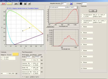
Main window in the irradiance measurement mode
The calculated output can be displayed and saved in two ways:
In the main Window the data is displayed as spectral irradiance in µWatt/cm2/nm versus wavelength, like in the graph above. Further, the result of up to 10 of the following output parameters is displayed in a separate window: radiometric quantities µWatt/cm2, µJoule/cm2, µWatt or µJoule, photometric quantities Lux or Lumen, color coordinates X, Y, Z, x, y, z, u, v and color temperature (figure 4). In Time Measurement mode, up to 8 functions can be displayed simultaneously against time. For each function, a different radiometric, photometric or color coordinate output parameter and/or wavelength range may be selected, as well as a different spectrometer channel. |
Cosine corrector
The cosine corrector (diffuser) is mainly used to measure radiation and light. Owing to diffraction in the diffusing material, a receiving characteristic of the incident irradiation close to Lambert distribution is reached. Lambert distribution is significant for light measurement.
The cosine corrector has an O.D. barrel with a black oxide finish, and screw on to the end of an SMA terminated optical fibre. Each corrector has SMA905 connectors for convenient coupling to optical fibres.
Radiant and luminous flux, radiant and luminous intensity and Irradiance / Illuminance can be measured with a cosine corrector. An important assumption in this calculation is that the source should be an isotropic point source. | | |
| | |
Integrating sphere– getSphere-IRRAD
Integrating spheres generally function as a light collector. The collected light is used as a a measurement source in the getSphere-IRRAD. The basic principle of operation is that light enters the integrating sphere through the sample port, goes through multiple reflections and is scattered uniformly around the interior of the sphere. The detection fiber optics are SMA-coupled to the port at the side of the sphere which is viewing illumination on a baffle, independent of the angular properties of the light at the sample port. The baffle prevents first reflections to enter the detection fiber.
The getSphere-IRRAD can be used to measure light sources (Laser, LED and Halogen Lamps). For the irradiance measurements of LED’s a special adapter was developed to be connected to the getSphere-50-IRRAD. The adapter can hold 3, 5 and 8 mm LED’s in the correct and reproducible position inside the sphere.
So it is possible to measure the total luminous flux of a LED correctly. | | 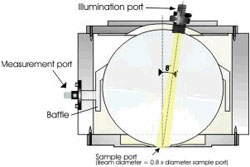 |
| | |
getLight-Hal-Cal - calibrated light source
The getLight-Hal-CAL is a calibrated light source for the VIS/NIR spectral range (350-1095 nm). This NIST-traceable calibrated light source is developed for use with all getSpec spectrometers to be used in measuring absolute spectral intensity. The getLight-Hal-CAL comes with a cosine corrector with SMA adapter. The software includes one calibration file for calibration with the cosine corrector in ASCII format. The calibration file can be imported in the IRRAD application software, developed to make your spectrometer system a spectroradiometer.
A special version of the calibrated light source, the getLight-Hal-Cal-ISP, is available to couple the getSphere-50-IRRAD to the light source.
Attention: The getLight-HAL-CAL cannot be used as an illumination source for spectral absorbance, transmittance and reflectance measurements. | | |
Perform absolute irradiance measurements using the getLight-Hal-Cal
1. Start the getSoft software, and click the “Start” button in the main window.
2. Connect a fiber to the Spectrometer input port.
3. Start the Absolute Irradiance Application software by clicking the menu option: Application/Absolute Irradiance. Click the “Perform Intensity Calibration” button.
4. Select the spectrometer channel that will be calibrated, the calibration lamp file and enter the diameter of the fiber/cosine corrector or integrating sphere sample port that is used. Use 3900 µm for cosine corrector.
5. Turn on the reference light source . getLight-HAL-CAL. If a cosine corrector is used at the end of the fiber, mount it directly on the reference light source. The getLight-Hal-Cal is delivered with an inserted cosine corrector. So you can connect the fiber cable directly on the cosine corrector. If an integrating sphere is used at the end of the fiber, put the integrating sphere sample port over the light output port.
6. Verify that the calibration lamp is ON for at least 15 minutes, and click the “Start Intensity Calibration” button. Try to adjust the integration time while looking at the reference light, such that the maximum count over the wavelength range is around 14000 counts. It’s also possible to let getSoft search for an optimal integration time by clicking the ‘AC’ button.
7. Adjust the Smoothing Parameter to optimize smoothing for the Fiber/Slit diameter that is used.
8. If a good reference signal is displayed, click the white “Save Reference” button. A white line will mark the reference spectrum. Then switch off the calibration lamp, wait until the spectrum becomes flat, near the bottom of the scale, and click the black button to save a dark spectrum. A black line will mark the dark spectrum.
9. Click the “Save Intensity Calibration” button. A dialog shows up in which the current settings in this intensity calibration are shown. If the calibration has been performed with diffuser, the intensity calibration data will be saved to an ASCII file with extension *.dfr, with bare fiber this extension will be *.fbr. The name of the intensity calibration file can be entered after clicking the “Save As” button.
10. Switch to the Irradiance Chart TAB to enter the hardware setup and select the colorimetric, radiometric, photometric and/or peak parameters of interest. Then click OK.
11. Measure the output parameters in the experiment. If needed, change the integration time, such that the maximum in Scope Mode is around 14000 A/D Counts. Block the light path to the spectrometer, and save a dark spectrum. If the (ir)radiance of the light to be measured needs to be displayed against time, click the time measurement TAB in the settings.
12. The intensity calibration as performed under point 9 can be loaded in future experiments by selecting the option “Load Intensity Calibration”. After loading an intensity calibration, a dark spectrum needs to be saved before switching to Irradiance mode.
|
Hardware setup for irradiance measurements
In the table below, the radiometric parameters that can be measured in getSoft are listed. Note that a wavelength range needs to be specified over which the parameter spectral output will be integrated. In the first column (Hardware setup), “inside sphere” refers to measurements that are done with the light source inside an integrating sphere, while “outside sphere or cc” refers to measurements that are done with a light source at a certain distance from the sphere or with a cosine corrector. |
| Hardware Setup | Parameter | Unit | Description |
| inside sphere | Radiant Flux (Power emitted) | µWatt | Total optical power emitted from a source |
| inside sphere | Energy emitted | µJoule | Total optical energy emitted from a source, calculated by multiplication of the power with the integration time |
| outside sphere or cc | Radiant Flux (Power emitted) | µWatt | Total optical power emitted from a source, calculated by multiplication of radiant intensity with the solid angle of the light source |
| outside sphere or cc | Energy emitted | µJoule | Total optical energy emitted from a source, calculated by multiplication of the power with the integration time |
| outside sphere or cc | Radiant Intensity | µWatt/sr | Optical power per unit solid angle, calculated by multiplication of irradiance with the square distance between point source and diffuser surface |
| outside sphere or cc | Power received | µWatt | Power received at diffuser surface |
|
|
Last change 08/14/2007 09:19 AM
Copyright (c) getAMO 2024
|
|
|
|